Network Topology Diagram Generator
Use the network topology diagram generator to map devices, links and network boundaries. Choose a physical or logical view, name the connections and review the resulting topology against your inventory.
SEE ACADRAW IN ACTION
Science drawing, from idea to editable figure
Create a science illustration with AI. Refine drawings, build editable diagrams, and convert images to SVG.
Demos play as you scroll into view. Choose a feature to explore.
Trusted by students & researchers from 480+ universities
A global community spanning 60+ countries and regions, from QS top-ranked universities to leading research institutes
























University logos belong to their respective institutions and are shown solely to illustrate our user community. They do not imply any partnership or endorsement.
Tool overview
Explore the use cases, workflow, and key things to know.
Connection clarity
Keep device roles and endpoint pairs explicit.
One view at a time
Separate physical cabling from logical segmentation.
Inventory-based review
Compare the drawing against your supplied records.
Concept reference
Network topology: a small office star
A conceptual office layout connects a router, a switch and three endpoints. It illustrates connectivity and device roles without assigning addresses, measured bandwidth or security guarantees.
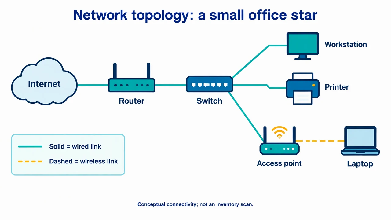
Network Topology Diagram Generator: reference key
Use the reference and definitions together. On a small screen, scroll the table horizontally.
| Element | Meaning | Review check |
|---|---|---|
| Node | A device or logical endpoint | Name its role rather than relying only on an icon. |
| Link | A connection between nodes | State whether it is physical, wireless or a logical relationship. |
| Switch | A device connecting local network endpoints | A shared box does not document VLAN membership by itself. |
| Router | A boundary between networks | Distinguish routing from switching roles. |
| Segment | A defined logical or physical network region | Label the boundary and the meaning of membership. |
| Legend | The meaning of line styles and symbols | Keep link meaning consistent across the drawing. |
Network Topology Diagram Generator: plan the visual
Use the network topology diagram generator to map devices, links and network boundaries. Choose a physical or logical view, name the connections and review the resulting topology against your inventory.
Choose physical or logical scope
A cabling view answers where equipment is connected. A logical view answers how segments and routing relationships are organized. Tell the network topology diagram generator which view to create, then avoid mixing cabinet locations with unlabelled trust boundaries.
Use an explicit connection list
List node names and each endpoint pair before generating the diagram. Specify whether a line means a cable, radio link, tunnel or selected data path. If you lack verified addresses or interface names, omit them rather than adding plausible numbers.
Read boundaries as design claims
A VLAN outline, firewall or subnet boundary conveys more than visual grouping. Identify the actual configuration behind it. The diagram can document intended connectivity, but it cannot prove reachability, access control or resilience without checking the network.
Common mistakes to avoid
Treating device icons as a live inventory
A generated layout does not discover equipment or validate its configuration. Start from a maintained inventory.
Drawing every link as traffic direction
An undirected physical cable and a directional application flow have different meanings. Use the right view and legend.
Assuming two links guarantee redundancy
Shared power, upstream dependencies and configuration can defeat a backup path. State the assumptions rather than using extra lines as proof.
Network Topology Diagram Generator: from brief to draft
Reading the reference is free. Generating a new draft requires an account and available credits. See current pricing.
Choose Science Drawing for an illustrated draft, or Editable Diagram for separate shapes and labels. Review all definitions, labels and connections before sharing.
- 1
List devices and links
Supply node roles, endpoint pairs and the physical or logical scope.
- 2
Draft the topology
Use the network topology diagram generator with named links and explicit boundaries.
- 3
Reconcile with the inventory
Check interfaces, paths and annotations against your current configuration.
Example brief for the network topology diagram generator
Original educational illustration on white, 1280x720 landscape, crisp vector-like editorial style, navy readable English labels, teal and amber accents, generous whitespace. Render all shapes, labels and arrows directly in the image. No third-party artwork, brand, logo, screenshot or measured result. Title 'Network topology: a small office star'. Cloud 'Internet' connects to 'Router', then to central 'Switch'. From Switch three separate lines reach 'Workstation', 'Printer', 'Access point'. Access point has a dashed wireless line to 'Laptop'. Label legend 'Solid = wired link', 'Dashed = wireless link'. Keep all links clean and unambiguous, no directional traffic arrows. Footer 'Conceptual connectivity; not an inventory scan'. No IP addresses or brands.
Use this prompt in the generatorNetwork Topology Diagram Generator: common questions
Does the network topology diagram generator scan my network?
No. It drafts a topology from the device and connection description that you supply.
Can I illustrate a star, mesh or ring?
Yes. Describe the actual node connections and label a hybrid arrangement when the network combines patterns.
Can I include VLANs or subnets?
Yes. Supply verified membership and boundaries, and distinguish the logical model from physical cabling.
Does a diagram establish network security?
No. Connectivity, policy enforcement and configuration need separate validation.
Sources and editorial notes
Prepared by the AcaDraw product team. Source and diagram check: . This is a simplified educational model; independent expert review has not been completed. AI-generated drafts need checking against reliable references.
Explore the network topology diagram guide
A conceptual office layout connects a router, a switch and three endpoints. It illustrates connectivity and device roles without assigning addresses, measured bandwidth or security guarantees.
Network Topology: Physical Links and Logical Connections