Use Case Diagram Generator
Use the use case diagram generator to map external actors and their goals within a named system boundary. Keep user capabilities separate from screen flows and internal implementation details.
SEE ACADRAW IN ACTION
Science drawing, from idea to editable figure
Create a science illustration with AI. Refine drawings, build editable diagrams, and convert images to SVG.
Demos play as you scroll into view. Choose a feature to explore.
Trusted by students & researchers from 480+ universities
A global community spanning 60+ countries and regions, from QS top-ranked universities to leading research institutes























University logos belong to their respective institutions and are shown solely to illustrate our user community. They do not imply any partnership or endorsement.
Tool overview
Explore the use cases, workflow, and key things to know.
Goal-based scope
Describe capabilities rather than individual clicks.
External roles
Keep actors outside the named system boundary.
Reviewable relationships
Use include and extend only when their meaning is clear.
Concept reference
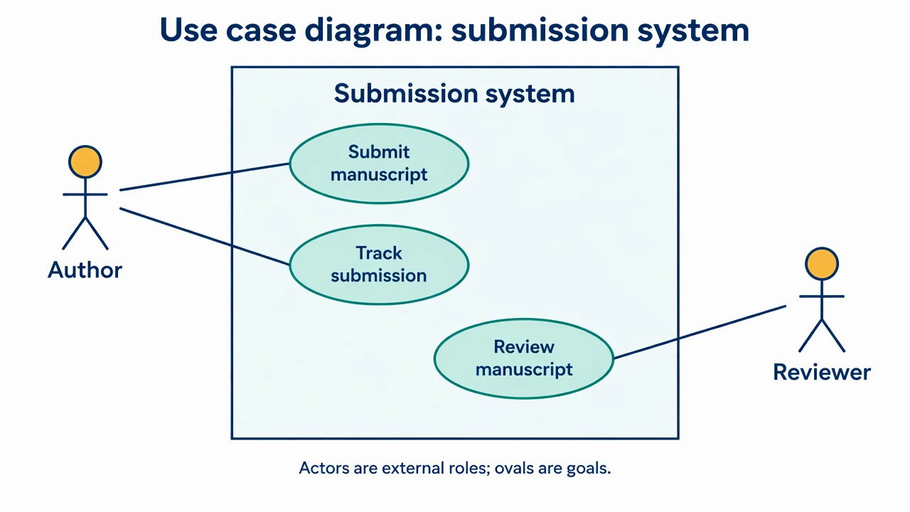
Use case diagram: a submission system
An author and reviewer sit outside a system boundary containing three goal-oriented use cases. Plain associations indicate participation rather than message direction.
Use Case Diagram Generator: reference key
Use the reference and definitions together. On a small screen, scroll the table horizontally.
| Element | Meaning | Review check |
|---|---|---|
| Actor | An external role interacting with the system | A role can be a person or another system. |
| Use case | A capability serving an actor goal | Use a verb phrase that describes a meaningful outcome. |
| Boundary | The system whose scope is being modeled | Keep external actors outside the rectangle. |
| Association | Participation in a use case | Do not read a plain line as an execution sequence. |
| Include | A reused behavior required by the base use case | Use it deliberately; the dashed arrow points to the included case. |
| Extend | Conditional behavior extending a base use case | State the condition; the arrow points to the extended base. |
Use Case Diagram Generator: plan the visual
Use the use case diagram generator to map external actors and their goals within a named system boundary. Keep user capabilities separate from screen flows and internal implementation details.
Start from goals rather than screens
Submit a manuscript is a goal; click a button is an interface action. Give the use case diagram generator the external roles and outcomes the system supports. Keep screen names and internal service calls for a different view.
Name the boundary explicitly
The same organization can be inside one system model and outside another. A boundary label explains what the diagram includes. An actor is a role in the interaction, so one person can play more than one role without requiring the roles to be merged.
Use include and extend sparingly
Plain actor associations are often enough for a scope overview. Include describes reused required behavior, while extend adds conditional behavior to a base case. Neither relationship should be used just to arrange ovals or to show chronological steps.
Common mistakes to avoid
Putting internal components outside as actors
A database inside the modeled system is not an external actor just because it has its own icon.
Using associations as a flowchart
A plain line indicates participation. It does not tell readers which goal happens first.
Reversing include and extend
Check the target of each dashed arrow and the intended semantics rather than choosing a familiar-looking label.
Use Case Diagram Generator: from brief to draft
Reading the reference is free. Generating a new draft requires an account and available credits. See current pricing.
Choose Science Drawing for an illustrated draft, or Editable Diagram for separate shapes and labels. Review all definitions, labels and connections before sharing.
- 1
Define actors and goals
Supply external roles, supported outcomes and the named system scope.
- 2
Draft the scope view
Use the use case diagram generator with plain associations before adding special relationships.
- 3
Review each relationship
Check participation, boundary placement and include/extend conditions against requirements.
Example brief for the use case diagram generator
Original educational illustration on white, 1280x720 landscape, crisp vector-like editorial style, navy readable English labels, teal and amber accents, generous whitespace. Render all shapes, labels and arrows directly in the image. No third-party artwork, brand, logo, screenshot or measured result. Title 'Use case diagram: submission system'. One large rectangle labeled 'Submission system'. Inside three separate ovals 'Submit manuscript', 'Track submission', 'Review manuscript'. Outside left stick actor labeled 'Author' connects by plain undirected lines to first two ovals. Outside right stick actor labeled 'Reviewer' connects to Review manuscript oval. All actors outside rectangle. No arrows, no include/extend edges, no databases or UI screens. Footer 'Actors are external roles; ovals are goals'.
Use this prompt in the generatorUse Case Diagram Generator: common questions
What does the use case diagram generator create?
It drafts a scope view showing external roles, their goals and a system boundary from your requirements.
Can another system be an actor?
Yes, if it is external to the chosen system boundary and interacts with it in a defined role.
Does a use case diagram show execution order?
No. Use a sequence diagram or process view to describe ordered interactions.
Do I need include and extend?
Only when those relationships clarify the model. A simple actor-to-goal diagram can be more useful for an initial scope discussion.
Sources and editorial notes
Prepared by the AcaDraw product team. Source and diagram check: . This is a simplified educational model; independent expert review has not been completed. AI-generated drafts need checking against reliable references.
Explore the use case diagram guide
An author and reviewer sit outside a system boundary containing three goal-oriented use cases. Plain associations indicate participation rather than message direction.
Use Case Diagrams: Actors, Goals, and System Boundaries