Microfluidic Chip Diagram Generator
Use a microfluidic chip diagram generator to map inlets, channels, a mixing junction and outlet. Draft a conceptual layout without fabricating dimensions, pressure or device performance.
SEE ACADRAW IN ACTION
Science drawing, from idea to editable figure
Create a science illustration with AI. Refine drawings, build editable diagrams, and convert images to SVG.
Demos play as you scroll into view. Choose a feature to explore.
Trusted by students & researchers from 480+ universities
A global community spanning 60+ countries and regions, from QS top-ranked universities to leading research institutes
























University logos belong to their respective institutions and are shown solely to illustrate our user community. They do not imply any partnership or endorsement.
Tool overview
Explore the use cases, workflow, and key things to know.
Define the purpose
State whether the figure explains a setup, process, interpretation or reporting boundary.
Label the convention
Explain what each arrow, line, color or control means.
Review the limits
Keep generated visuals separate from real measurements and source files.
Concept reference
Microfluidic chip: inlets, channels, and outlet
A conceptual chip layout with sample and buffer inlets, a mixing junction, serpentine channel and collected-stream outlet. It shows direction only, not dimensions or measured flow.
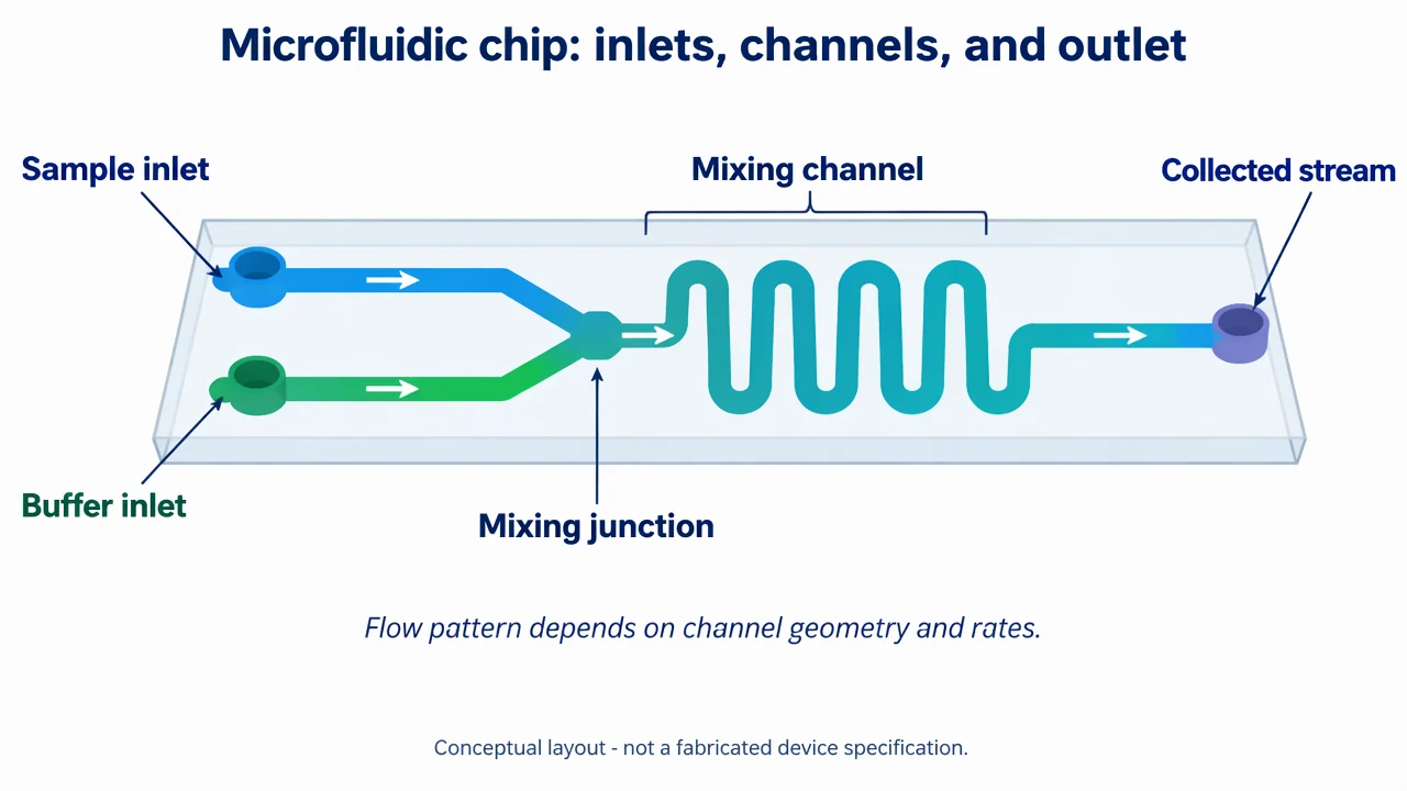
Microfluidic Chip Diagram Generator: reference key
Use the reference and definitions together. On a small screen, scroll the table horizontally.
| Element | Meaning | Review check |
|---|---|---|
| Inlet | A fluid entry point | Name the supplied stream and boundary condition. |
| Channel | The constrained flow path | Draw geometry clearly and avoid unverified dimensions. |
| Junction | A point where streams meet | Mixing depends on geometry, rates and transport. |
| Serpentine channel | A longer path for residence or mixing | Do not infer performance from the shape alone. |
| Outlet | The collection or downstream connection | State what is collected and how it is analyzed. |
| Flow arrow | The intended direction | It is not a measured velocity field. |
Microfluidic Chip Diagram Generator: plan the content
Use the microfluidic chip diagram generator to make the flow path and boundary conditions readable. Channel geometry, rates and surface effects determine behavior; a clean drawing is not a fabricated specification.
Start with the purpose of the microfluidic chip diagram
A useful microfluidic chip diagram begins with one question. Decide whether the visual should explain setup, process order, interpretation or a reporting boundary. A crowded diagram can contain accurate icons and still fail if the reader cannot tell what to notice first. The reference image is deliberately bounded. It uses labels and arrows to organize a teaching explanation, not to substitute for a protocol, a result file or a validated device. Write the scope in the caption before adding detail.
Separate the visual convention from the claim
Colors, line weights and arrows help a reader follow a microfluidic chip diagram, but they do not automatically represent measured magnitude or certainty. Define what an arrow means and state when a panel is illustrative. If the figure includes a control, label what decision that control supports. This distinction matters when a familiar visual resembles a result. A band, test line, gate, signal or property label can look authoritative even when it is only a teaching placeholder. Preserve that boundary in the legend and surrounding text.
Keep provenance and review visible
Before sharing a microfluidic chip diagram, compare every label with a reliable source and the actual question. Record the source image, method context, assumptions and edits. If the topic involves an assay or material, keep experimental observations in their own record rather than filling gaps with a plausible generated visual. A concise reference key makes review easier. It tells collaborators which terms are structural, which are process events and which are interpretations. That key is often more valuable than adding another decorative arrow.
Common mistakes in a microfluidic chip diagram
Separate the visual convention from the claim
Colors, line weights and arrows help a reader follow a microfluidic chip diagram, but they do not automatically represent measured magnitude or certainty. Define what an arrow means and state when a panel is illustrative. If the figure includes a control, label what decision that control supports. This distinction matters when a familiar visual resembles a result. A band, test line, gate, signal or property label can look authoritative even when it is only a teaching placeholder. Preserve that boundary in the legend and surrounding text.
Keep provenance and review visible
Before sharing a microfluidic chip diagram, compare every label with a reliable source and the actual question. Record the source image, method context, assumptions and edits. If the topic involves an assay or material, keep experimental observations in their own record rather than filling gaps with a plausible generated visual. A concise reference key makes review easier. It tells collaborators which terms are structural, which are process events and which are interpretations. That key is often more valuable than adding another decorative arrow.
Use the draft as a reviewable starting point
The microfluidic chip diagram tool helps turn a brief into a visual draft. It cannot decide whether a sample is valid, whether a mechanism is complete or whether a conclusion follows from a measurement. Ask a domain reviewer to check the final figure when the visual will guide an experiment, publication or health decision. Export the figure with a caption that names the scope and limits. Keep real data, source files and calculation records linked to the final version. A transparent workflow lets readers understand what the image explains and what it leaves unanswered.
Microfluidic Chip Diagram Generator: from brief to reviewed draft
Reading the reference is free. Generating a new draft requires an account and available credits. See current pricing.
Choose Science Drawing for an illustrated draft, or Editable Diagram for separate shapes and labels. Review all definitions, labels and connections before sharing.
- 1
Write a bounded brief
Describe the scope, participants and visual conventions needed for this figure.
- 2
Generate a structured draft
Choose an illustrated or editable layout, then keep labels and arrows explicit.
- 3
Review before sharing
Compare the result with the source, method or design record and revise unsupported claims.
Example brief for a microfluidic chip diagram
Original microfluidic chip diagram, white 1280x720 landscape, crisp vector-like scientific style, large readable English labels. Title 'Microfluidic chip: inlets, channels, and outlet'. Show a transparent chip rectangle with two labeled inlets 'Sample inlet' and 'Buffer inlet' entering separate channels, a central mixing junction, a serpentine channel labeled 'Mixing channel', and one outlet labeled 'Collected stream'. Use arrows to show fluid direction left to right. Add a small note 'Flow pattern depends on channel geometry and rates'. Footer 'Conceptual layout - not a fabricated device specification'. No pressure values, no fabricated dimensions, no clinical claims, no logos or copied chip artwork. Render all labels, arrows and boundaries in image.
Use this prompt in the generatorMicrofluidic Chip Diagram Generator: common questions
What does the microfluidic chip diagram tool create?
It creates an educational draft from your description. It does not infer real measurements or validate an experiment.
Does the drawing specify a manufacturable chip?
No. It is a conceptual flow layout without dimensions, pressure limits or fabrication validation.
What should I review before sharing?
Check labels, directions, scope and the source-specific details in the microfluidic chip diagram figure.
Does it support real data analysis?
No. This page is for qualitative visual explanation and editable drafting, not computation from a data table.
Sources and editorial notes
Prepared by the AcaDraw product team. Source and diagram check: . This is a simplified educational model; independent expert review has not been completed. AI-generated drafts need checking against reliable references.
Read the microfluidic chip diagram guide
A microfluidic chip diagram should make the flow path and boundary conditions readable. Channel geometry, rates and surface effects determine behavior; a clean drawing is not a fabricated specification.
Microfluidic Chip Diagrams: Channels, Inlets, and Flow