Free Body Diagram Maker
Use the free body diagram maker to isolate a chosen object and show the external forces acting on it. Describe the contact surfaces, motion and any applied force before generating a draft. A free body diagram supports physical reasoning; it does not solve an unspecified problem or measure force magnitudes.
SEE ACADRAW IN ACTION
Science drawing, from idea to editable figure
Create a science illustration with AI. Refine drawings, build editable diagrams, and convert images to SVG.
Demos play as you scroll into view. Choose a feature to explore.
Trusted by students & researchers from 480+ universities
A global community spanning 60+ countries and regions, from QS top-ranked universities to leading research institutes
























University logos belong to their respective institutions and are shown solely to illustrate our user community. They do not imply any partnership or endorsement.
Tool overview
Explore the use cases, workflow, and key things to know.
Select one body
Name the object and identify the environment acting on it.
Label external forces
Keep velocity and acceleration arrows separate from force arrows.
Check the stated motion
Use equilibrium only when the physical conditions justify it.
Concept reference
Free Body Diagram Maker: a worked example
This free body diagram isolates a block sliding right at constant speed on a level rough surface. Weight points down, the normal force points up, the horizontal applied force points right and kinetic friction points left. For this stated case the opposing forces balance; equal arrow lengths are a qualitative convention, not measured values.
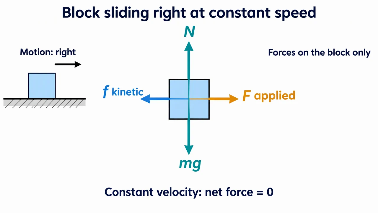
Free Body Diagram Maker: reference key
Use the reference and definitions together. On a small screen, scroll the table horizontally.
| Element | Meaning | Review check |
|---|---|---|
| Selected body | The object being isolated | Include forces on this body, not its reaction forces on other bodies. |
| Weight | Gravitational force on the body | Point toward the source of gravity; near Earth use the local downward direction. |
| Normal force | Contact force perpendicular to the surface | Do not assume its magnitude always equals weight. |
| Kinetic friction | Contact force opposing relative sliding | Use the sliding direction at the contact, not a guessed direction of acceleration. |
| Applied force | An externally imposed push or pull | Use the actual application direction and state any angle. |
| Net force | The vector sum of external forces | Constant velocity implies zero net force, not absence of forces. |
Free Body Diagram Maker: plan the content
Begin a free body diagram with a system boundary. Every included arrow must represent a force exerted on that selected body by something outside it.
Inventory interactions
List gravity, each contact and each applied push or pull before drawing. One physical interaction may contribute normal and friction components.
Choose axes after the forces
For an incline, axes along and perpendicular to the surface can simplify the later equations. The forces themselves do not rotate to match a convenient axis.
Check before calculating
A free body diagram is the setup for equations. Review signs and constraints before deriving accelerations or unknown forces.
Common mistakes in a free body diagram
Adding motion as a force
Velocity and acceleration describe motion. Neither is an additional force arrow on a free body diagram.
Putting an action-reaction pair on one body
The block pushes the floor and the floor pushes the block. Only the latter belongs on the block’s isolated diagram.
Assuming normal always equals weight
Other vertical forces, angled surfaces or vertical acceleration can change the normal force. The reference equality applies only to the stated level case.
Free Body Diagram Maker: from brief to reviewed draft
Reading the reference is free. Generating a new draft requires an account and available credits. See current pricing.
Choose Science Drawing for an illustrated draft, or Editable Diagram for separate shapes and labels. Review all definitions, labels and connections before sharing.
- 1
Specify the physical situation
Tell the free body diagram maker which body to isolate, which contacts exist and how the object moves.
- 2
Generate the force inventory
Request only external forces on the selected body, with a separate context sketch if useful.
- 3
Review directions and assumptions
Confirm the free body diagram matches the case before using it to write Newton’s second-law equations.
Example brief for a free body diagram
Draw a free body diagram for one block sliding right at constant velocity on a level rough surface under a horizontal applied force. Show only forces on the block: normal up, weight down, applied force right and kinetic friction left. Indicate that opposing forces balance in this stated case. Put motion in a separate context sketch and do not add velocity as a force.
Use this prompt in the generatorFree Body Diagram Maker: common questions
What does the free body diagram maker create?
It creates a draft force diagram from the situation you describe. It is not an automatic solver or a source of measured force values.
Does constant speed mean no forces act?
No. Constant velocity means the net force is zero. Several nonzero forces may balance. Constant speed on a curved path can still involve acceleration.
Should I include a velocity arrow in a free body diagram?
Keep it outside the force inventory or in a separately labeled context sketch so it cannot be mistaken for a force.
Can the free body diagram maker handle an incline?
Yes, when you specify the selected object, slope, contacts and applied forces. Review normal and friction directions carefully.
Is friction always opposite the applied force?
No. Kinetic friction opposes relative sliding at the contact; its direction must be inferred from the physical situation.
Sources and editorial notes
Prepared by the AcaDraw product team. Source and diagram check: . This is a simplified educational model; independent expert review has not been completed. AI-generated drafts need checking against reliable references.
Read the free body diagram guide
Begin a free body diagram with a system boundary. Every included arrow must represent a force exerted on that selected body by something outside it.
Free Body Diagrams: Forces, System Boundaries, and Equilibrium